
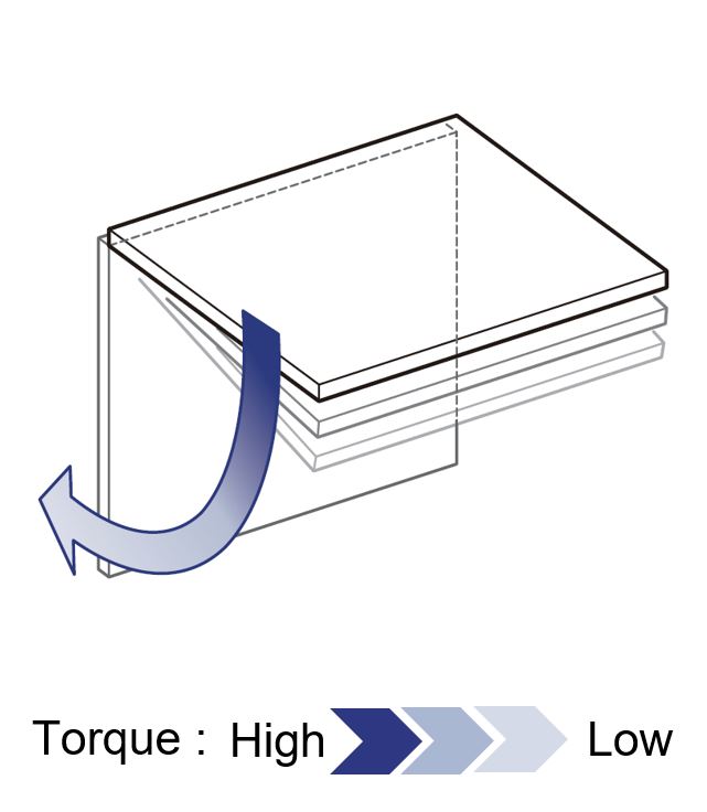
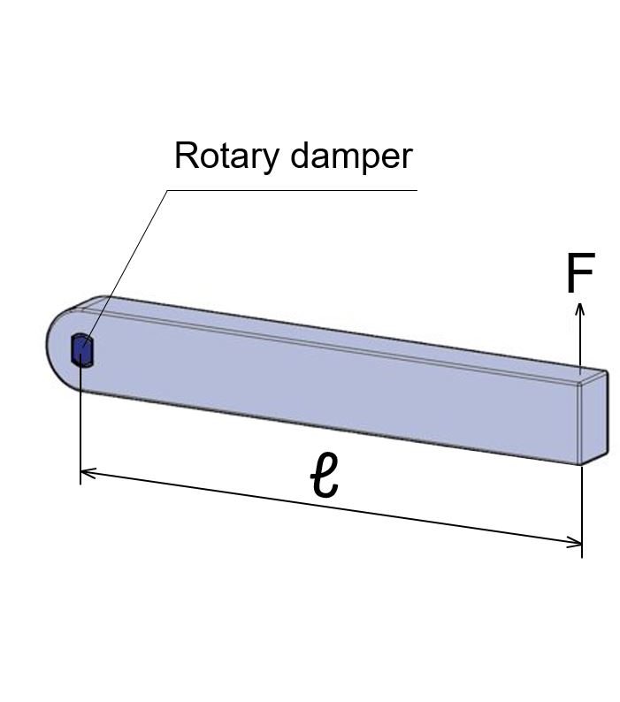
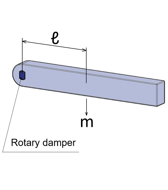
Horizontal use
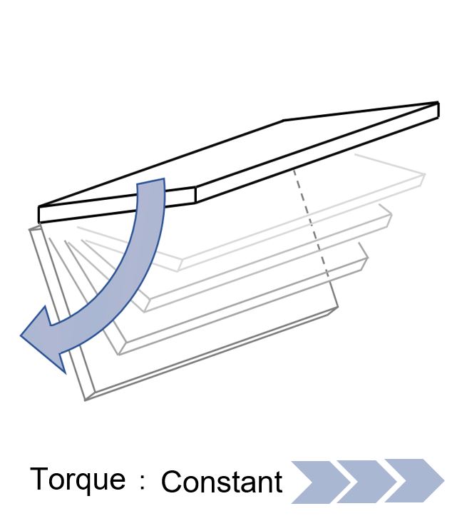
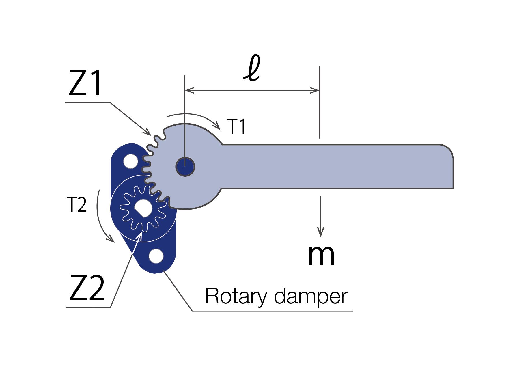
Horizontal & Vertical use
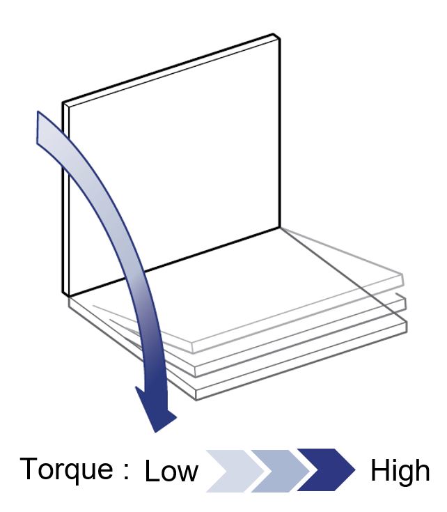
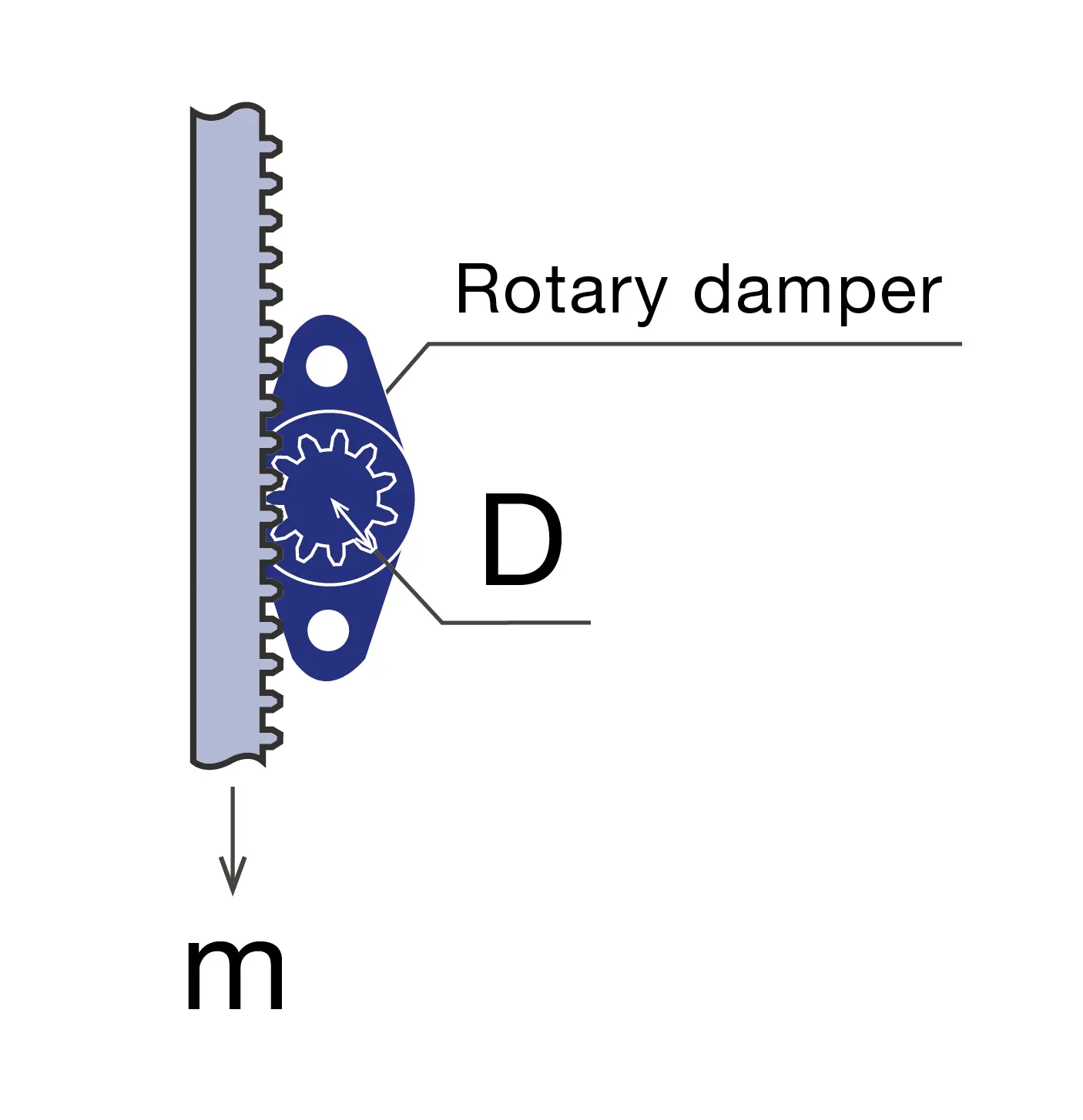
Vertical use
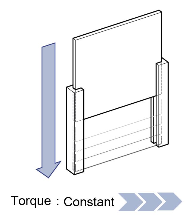
Continuous rotation
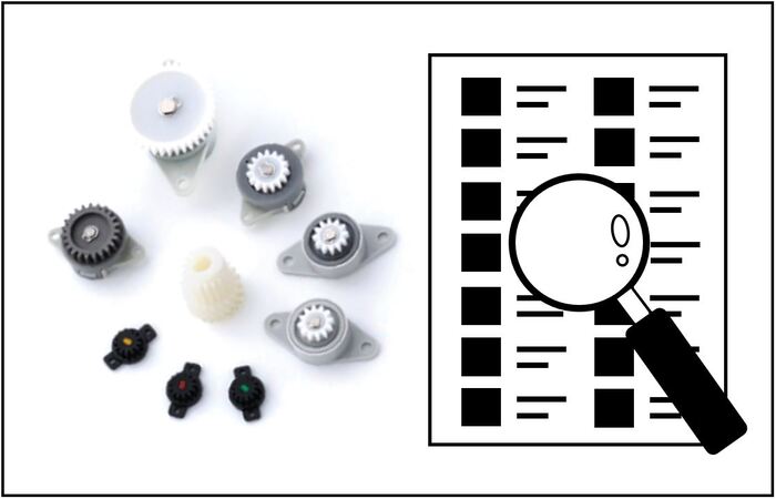

Rotary damper applications
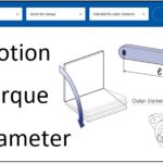
Rotary damper selection guide
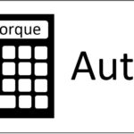
Rotary damper torque auto-calculation
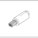
Small Diameter High Torque Rotary Damper | TD100 …
The Difference Between a Rotational Damper and a …
What is a Rotary Damper?
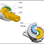
Rotary Dampers | How Does It Work?

Soft Close Rotary Damper Design | How to Select I…
Soft Close Rotary Damper Design | How to Select I…
One-Way Rotary Damper | Continuous Rotation Damper
![]()
Copyright © Rotary dampers | TOK, Inc.. All Rights Reserved.