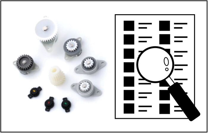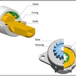
Torque calculation for rotary dampers is basically the same for both partial rotation angle dampers and continuous rotation dampers, but continuous rotation dampers (gear dampers) look more complicated due to the gears meshing with each other. In this explanation, we will clarify the torque calculation method for gear dampers.
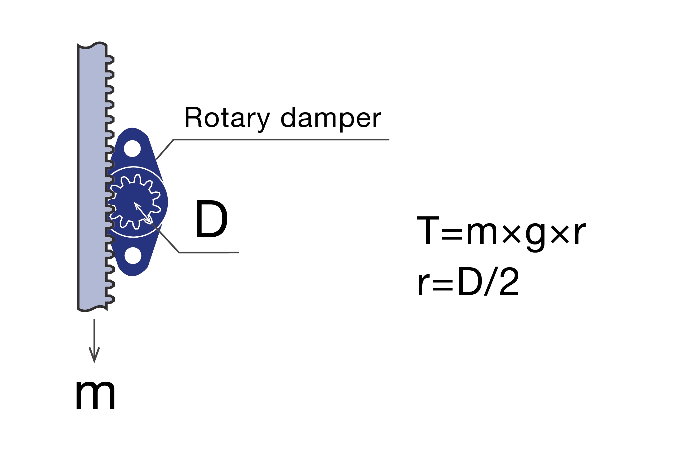
When you use gear dampers as a mechanical element of a rack and pinion, you need to calculate as follows.
Assuming the gears are always meshed with the rack and the system falls straight down, let m represent the weight of the rack gear and shutter assembled onto the rack which are the objects to fall down, and the gear pitch circle diameter of the rotary damper used as the pinion gear be D.
Since torque is calculated as radius × force, we calculate the radius r from the pitch circle diameter D.
r=D/2
When treating a fall down object as a torque, it is necessary to apply gravitational acceleration, so the torque calculation can be shown as follows.
T=m×g×r
Although the free fall occurs with the rack and shutter, the part connected to the rotary damper is the pitch, so it is appropriate to use the gear radius of the rotary damper as a parameter for torque, assuming that they are meshed based on the pitch circle. This calculation method is not limited to rack and pinion, but also applies when a pulley is assembled on the damper shaft and a wire is wound around it to slowly lower a heavy load. If the wire is suspended tangled to the outer diameter of the pulley and the heavy load is on the end of the wire, the weight of the heavy load is m and the radius of the pulley is r. You can automatically calculate the torque here.
As a supplement, the torque setting of our continuous rotation dampers is the torque when rotating at 20rpm or 30rpm, so if the rotation speed is faster than this, you should choose the rotary damper with low torque, and if the rotation speed is slower than this, you should choose it with high torque. Also, the guide used to fall the rack vertically generates a small amount of frictional resistance during falling. This becomes sliding resistance and the torque required for the rotary damper may be set lower than the result of this calculation. Since we do not add sliding resistance to the automatic calculation system, please we aware that there may be a slight error from the theoretical value when the rotary damper is mounted.
Summary of Torque Calculation Method for Rotary Dampers | In the Case of Free Fall
Until now, TOK has only opened the torque calculation method for partial angle rotation dampers and has not opened it for continuous rotation dampers (gear dampers), even in our catalog. In response to your requests, we have released a new automatic torque calculation page for continuous rotation dampers (gear dampers) which fall under their own weight. If you would like to use a spring to lift up gear dampers without free fall, please feel free to contact us for a different torque calculation method.
Related Articles
・Rotary damper torque auto-calculation
・Tips to determine a rotary damper torque
・Rotary Damper Torque Calculator | One Point Explanation
・One-Way Rotary Damper | Continuous Rotation Damper
・How to Amplify Torque with Gears When Rotary Damper Lacks Torque
フォームが表示されるまでしばらくお待ち下さい。
恐れ入りますが、しばらくお待ちいただいてもフォームが表示されない場合は、こちらまでお問い合わせください。

